Hey there,
Welcome (back) to my blog! If this is your first time here, this post is a continuation of my previous article on Physics Engines: Building a Cloth-like Interactive Mesh with MatterJS, P5JS. Today, we’ll explore how to apply a fill to the mesh or “cloth” we created earlier.
In the previous example, we built a 2D matrix of interacting points that formed a grid of particles and constraints using the Matter JS library. These particles interacted with each other and their environment through constraints like gravity, springs, cohesion and friction.
Now, let’s dive into how to visually “fill” this 2D mesh so that the cloth can occlude elements behind it and interact visually with other objects on the screen.
To start with I will simplify the amount of rows and columns aiming for a 3x3 cell grid.
Simplifying the Problem: A 3x3 Grid
To simplify the example, we’ll reduce our visualization to a 3x3 grid: three columns and three rows. This gives us:
- 9 cells
- Each cell with a width and height of widthOfCell = windowWidth / 3 and heightOfCell = windowHeight / 3.
Initially, it might seem intuitive to draw a rectangle for each cell, aligning its corners with the particle centers.
``` // attempt A inside the draw loop function draw() { noCursor(); background(255); fill(255, 0, 0); fill(0,0,255) textSize(44) textAlign(CENTER,CENTER) text("behind the curtains", width/2, height/2) for (var p of particles) { p.show(); }
// attempt A for (var p of particles){ fill(255) stroke(0,255,0) rect(p.body?.position.x,p.body?.position.y,width/amntRowsCols,height/amntRowsCols) }
for (var c of constraints) { c.show(); }
fill(0, 0, 255, 100); ellipse(mouseX, mouseY, 10, 10); } ```
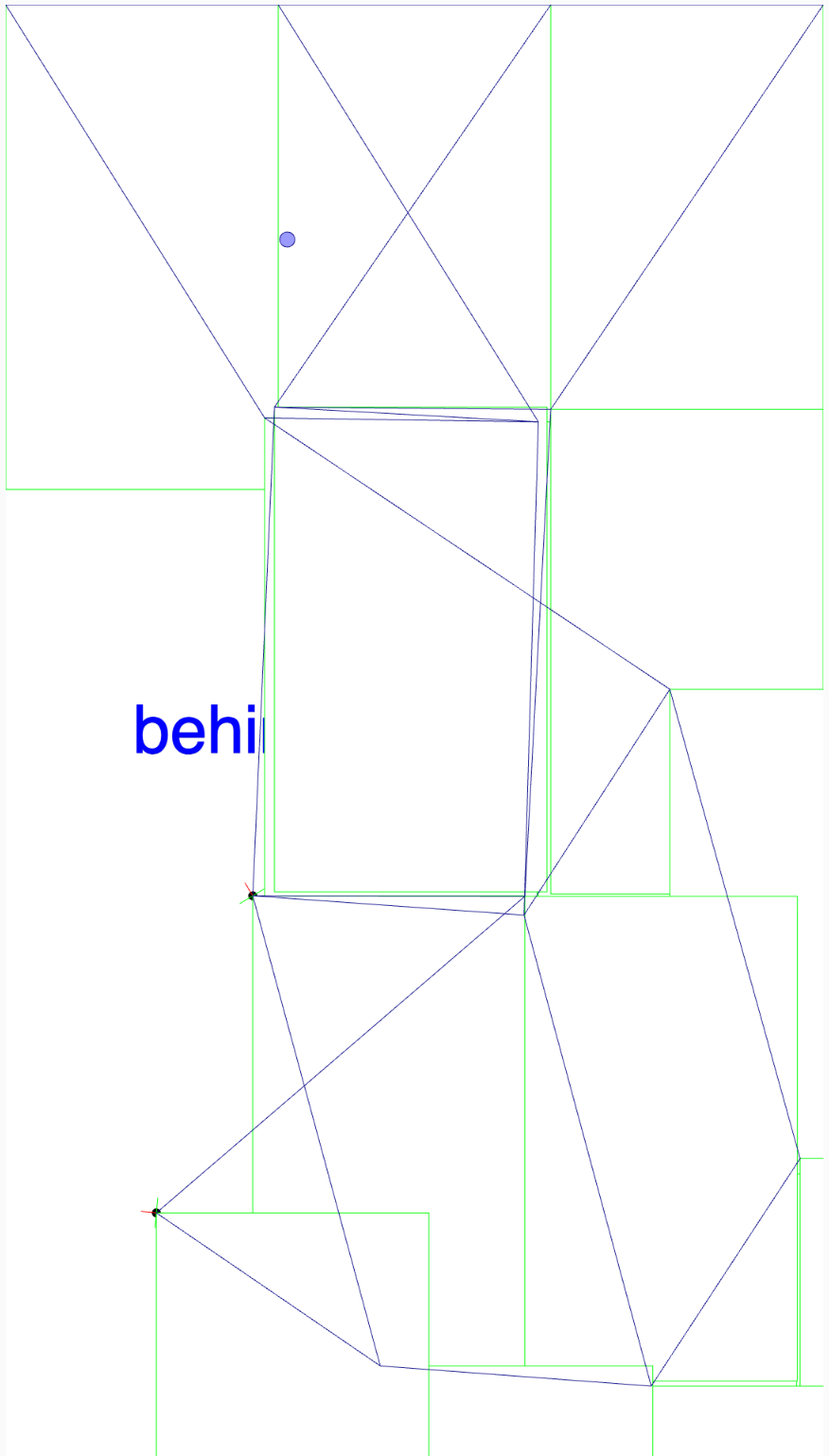
However, as you can see in the image bellow this approach creates some problems:
- The rectangles won’t deform like cloth.
- They’ll stay rigidly attached to their top-left corners, often overlapping or moving unnaturally.
While this method produces a unique aesthetic, we can achieve something closer to realistic cloth behaviour.
Drawing Complex Shapes with beginShape() and endShape()
A better approach is to use beginShape() and endShape() from p5.js. These functions allow us to define a shape by specifying the coordinates of its vertices. For this we can iterate through each of the particles in the particle system, bearing in mind that we will advance linearly through their indexes: → i[0], i[1], i[2], i[3] …
Here’s an example:
`` // attempt B using beginShape, endShape and a set of vertices // Begin defining the shape fill(255,0,0,220); // using now a bit of color with diminished oppacity beginShape(); for (var p of particles) { // Add a vertex at the particles' body's position vertex(p.body?.position.x,p.body?.position.y); } // Close the shape endShape(CLOSE); ``
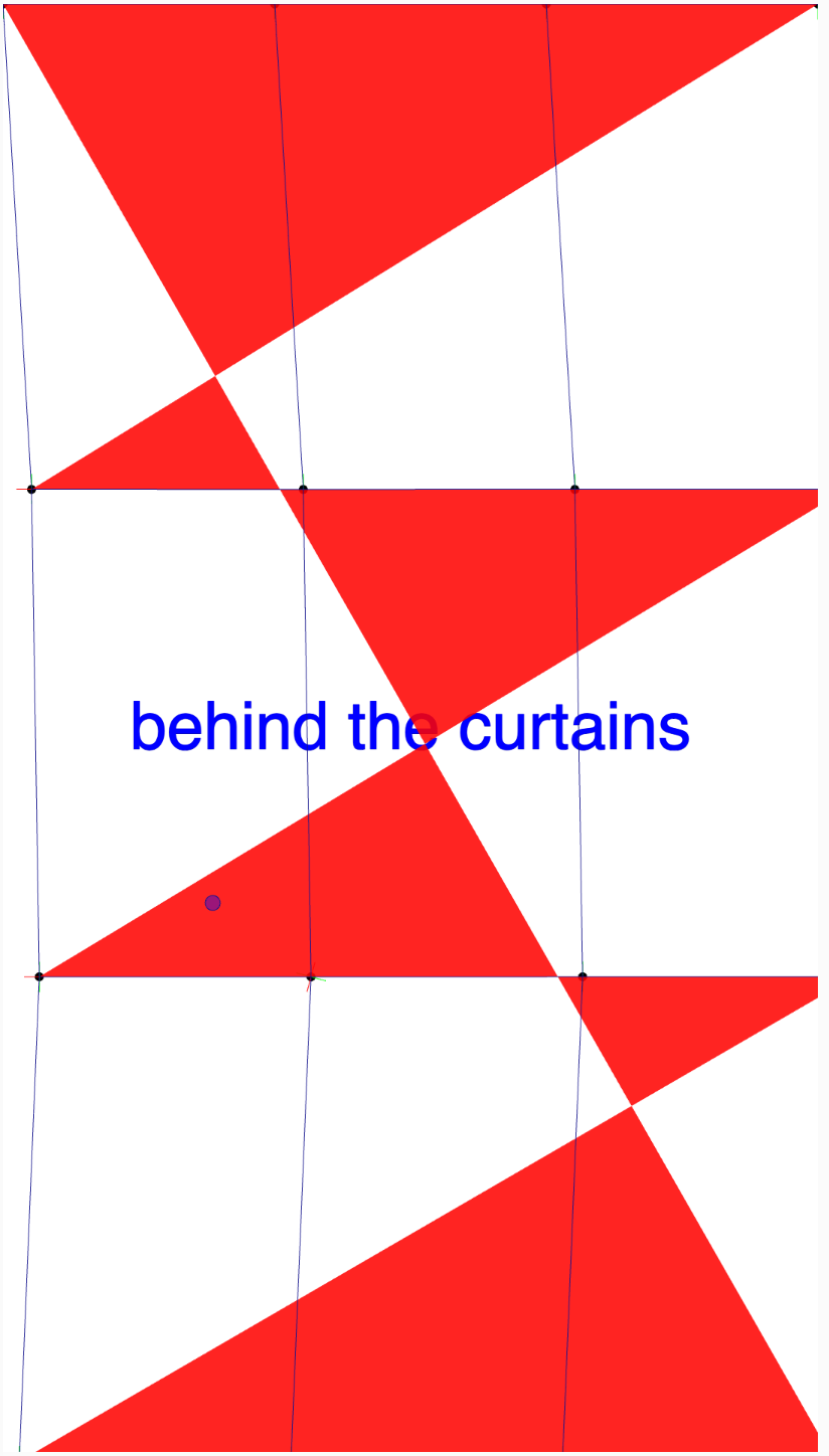
However, this first attempt doesn’t work as expected. Why? Take a look at the image and reflect on why:
The Problem: Zig-Zag Connections
If we iterate through the points linearly, we end up with a zig-zagging line rather than a smooth surface. Here’s what happens:
- The first row is drawn left-to-right: i[0] → i[1] → i[2] → i[3].
- The second row continues directly from the first: i[4] → i[5] → i[6] → i[7].
- This pattern repeats for subsequent rows.
The result is a jagged line connecting the rows diagonally.
The Solution: Grouping Neighbouring Points
To draw a deformable surface, we need to consider groups of neighbouring points and connect them properly.
Let’s “draw” the whole grid with text just to exemplify the set of points.
`` i[0] - i[1] - i[2] - i[3] | | | | i[4] - i[5] - i[6] - i[7] | | | | i[8] - i[9] - i[10] - i[11] | | | | i[12] -i[13] -i[14] - i[15] ``
To draw the first cell, we should grab the first set of points building a rectangle, for instance:
`` i[0] — i[1] | | i[4] — i[5] ``
Now we transfer this abstraction into code that is compatible with our existing implementation.
`` // attempt C brutforce finding sets of points fill(255,0,0,220); // using a bit of color with diminished oppacity stroke(255,255,0) strokeWeight(4) beginShape(); // brute force let p1 = particles[0].body.position let p2 = particles[1].body.position let p3 = particles[5].body.position let p4 = particles[4].body.position vertex(p1.x,p1.y) vertex(p2.x,p2.y) vertex(p3.x,p3.y) vertex(p4.x,p4.y) // Close the shape endShape(CLOSE); ``
And this ‘brute force approach’ works and looks like this for the first cell:
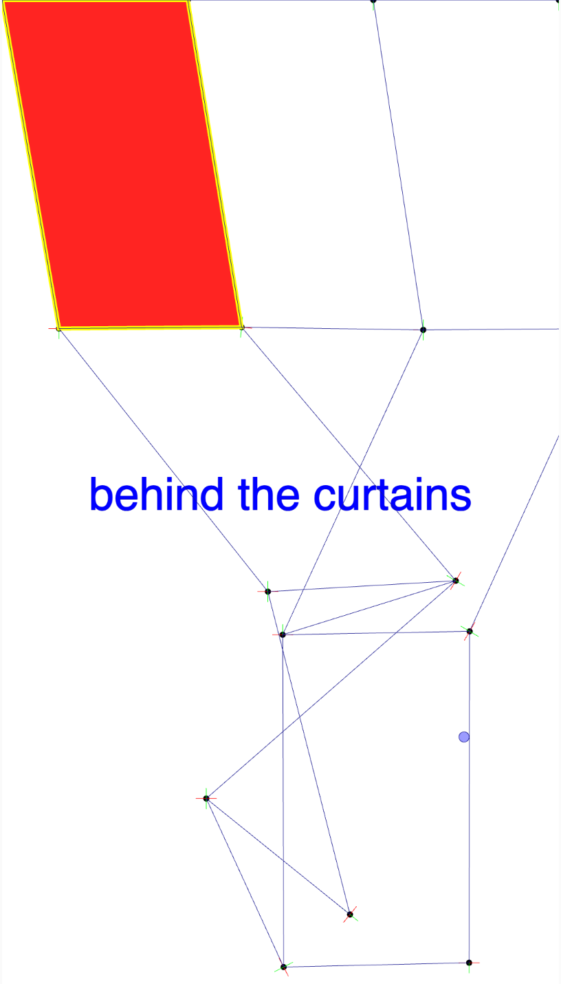
Don’t Worry we will soon write a good recursive algorithm to this for us. But let’s just do the mental exercise to understand better what an algorithm does or should do. To continue doing this mental exercise, we should define the subsequent cells using these points, then repeat for the next group:
- i[1], i[2], i[5], i[6]
- i[2], i[3], i[6], i[7]
- i[4], i[5], i[8], i[9]
- i[6], i[7], i[10], i[11]
Etc…
This approach works for a small grid, but as said, manually identifying groups for larger grids (e.g., 40x40) becomes impractical in a brute force fashion. Instead, we can write a recursive algorithm to dynamically determine the neighbouring points and draw the cells. Btw. these rectangular cells in Computer Graphics are known as Quads.
Ok, to keep our sketch clean I’ll pack the function to fill in the Quads iteratively:
``` // inside the draw function
...
// attempt D filling in the QUADS fillQuadsIterative(amntRowsCols,amntRowsCols) ...
// outside we declare the function to fill the quads function fillQuadsIterative(cols, rows) { fill(255, 0, 0, 220); // Quad fill color stroke(255, 255, 0); // Quad stroke color strokeWeight(2); // we use to for loops nested for (let y = 0; y < rows; y++) { for (let x = 0; x < cols; x++) { let i = y * (cols + 1) + x; // this one turns the x and y coordinates into the liner index, flattening the 2D array into 1D set // Get the four points forming the quad let p1 = particles[i].body.position; // Top-left let p2 = particles[i + 1].body.position; // Top-right let p3 = particles[i + cols + 2].body.position; // Bottom-right let p4 = particles[i + cols + 1].body.position; // Bottom-left // Draw the quad beginShape(); vertex(p1.x, p1.y); vertex(p2.x, p2.y); vertex(p3.x, p3.y); vertex(p4.x, p4.y); endShape(CLOSE); } } }
```
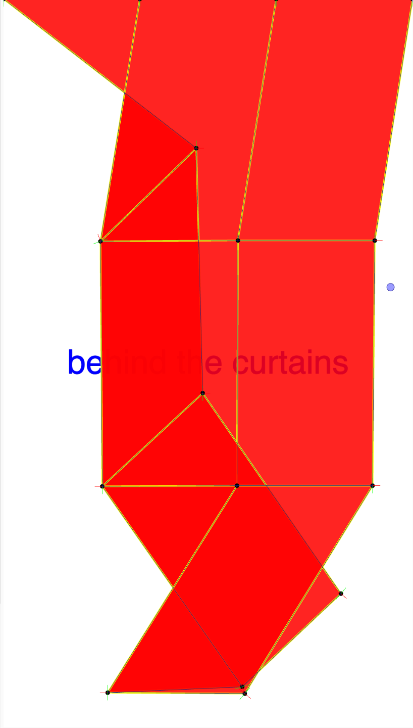
We can also use another variation which would be more suitable for more complex deformations, shapes or three dimensional systems. This approach focuses on filling in the Triangles instead of the Quads.
Improving Deformation with Triangles
Even with rectangles, our simulation now looks much better — each cell deforms as its vertices move. But for more realistic behaviour, we can switch to triangles, which allow for complex deformations.
Here’s how to adapt the algorithm:
- Divide each rectangle into two triangles.
- Define the vertices for each triangle.
- With these principle in mind let’s write the function fillTrianglesIterative and use it inside the draw loop
``` // inside the draw loop function we declare the function to fill the triangles iteratively ...
fillTrianglesIterative()
...
function fillTrianglesIterative(){
stroke(255,0,0); fill(255,200); // let's use white color with a bit of transparency // we will use two nested for loops for (let y = 0; y < amntRowsCols; y++) { for (let x = 0; x < amntRowsCols; x++) { let i = (x * (amntRowsCols + 1)) + y; // this one turns the x and y coordinates into the liner index, flattening the 2D array into 1D set
// Ensure that we stay within bounds and include the first row but we don't really need it // if (x < amntRowsCols && y < amntRowsCols) {
// Top-left triangle beginShape(); vertex(particles[i].body.position.x, particles[i].body.position.y); vertex(particles[i + 1].body.position.x, particles[i + 1].body.position.y); vertex(particles[i + amntRowsCols + 2].body.position.x, particles[i + amntRowsCols + 2].body.position.y); endShape(CLOSE);
// Bottom-right triangle beginShape(); vertex(particles[i].body.position.x, particles[i].body.position.y); vertex(particles[i + amntRowsCols + 2].body.position.x, particles[i + amntRowsCols + 2].body.position.y); vertex(particles[i + amntRowsCols + 1].body.position.x, particles[i + amntRowsCols + 1].body.position.y); endShape(CLOSE); // } } } } ```
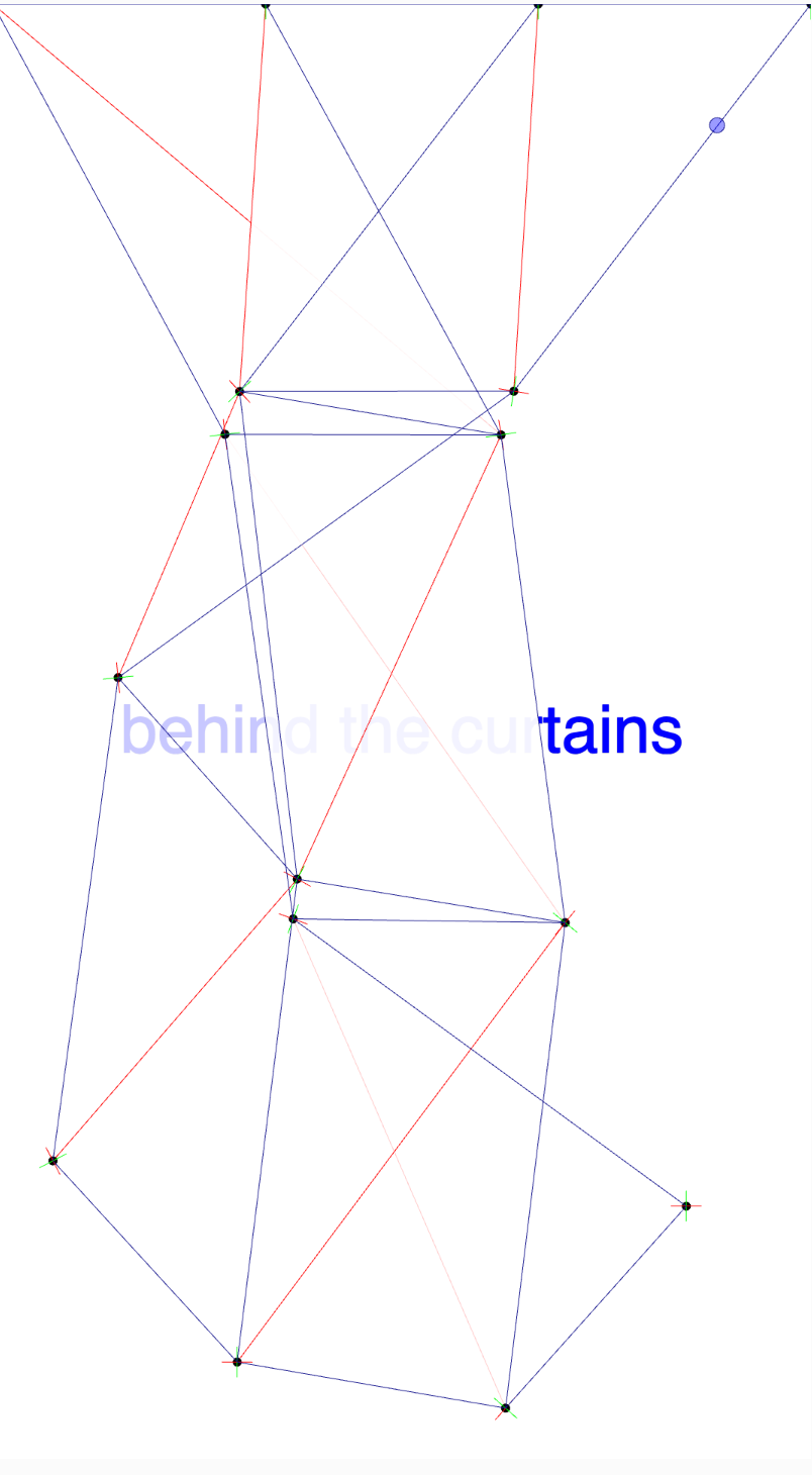
And this is how it looks after deforming the cloth a bit :)
Bringing It All Together
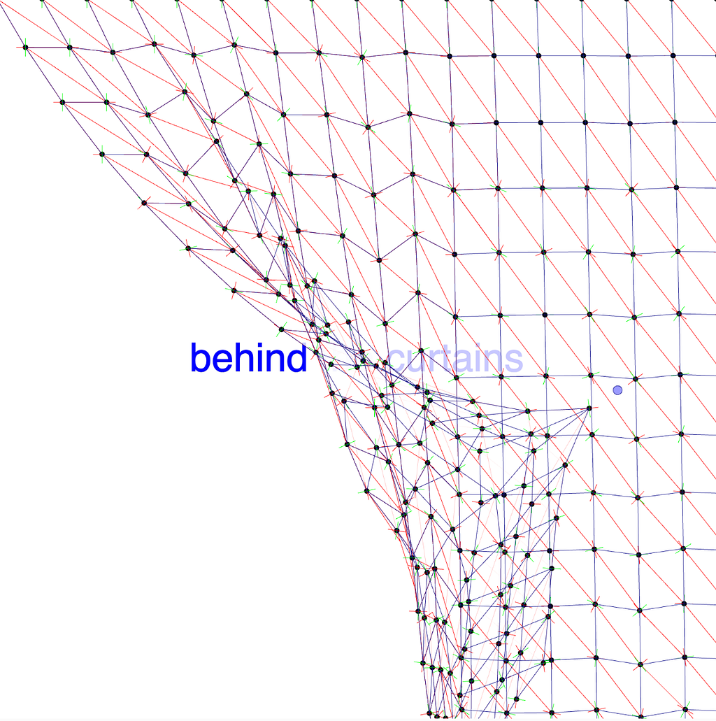
With the algorithm refined, we can integrate it into our original cloth simulation. Adding color and a background element further enhances the visuals. I already added this in the screenshots. You can review that in the shared code.
Bonus Challenge: Textures and Shaders
Instead of simply filling the shapes with color, can we apply an image as a texture? Try fragmenting an image into the rectangular or triangular sections and mapping it to the deformable shapes. Hint: Look into textures and shaders for this!
Full Code
You can find the complete code and interact with it here directly over the p5js editor.
And here:
``` // defines all elements from matter js engine // written by ndr3svt from sooft.studio based on Daniel Shiffman's tutorials on matterjs // find more stuff like this on Instagram : // https://www.instagram.com/ndr3svt/ // https://www.instagram.com/sooft.studio/
// defines all elements from matter js engine var Engine = Matter.Engine, World = Matter.World, Bodies = Matter.Bodies, Constraints = Matter.Constraint, Mouse = Matter.Mouse, MouseConstraint = Matter.MouseConstraint;
var engine; var world; var particles = []; var constraints = []; var mConstraint; let amntRowsCols = 3;
function setup() { var canvas = createCanvas(540, 960); engine = Engine.create(); world = engine.world; Matter.Runner.run(engine); let gridWidth = 540 / amntRowsCols; let gridHeight = 960 / amntRowsCols;
for (let y = 0; y <= amntRowsCols; y++) { for (let x = 0; x <= amntRowsCols; x++) { var isStatic = y === 0; // Fix particles in the first row var i = y (amntRowsCols + 1) + x; particles[i] = new Particle( 0 + gridWidth x, 0 + gridHeight * y, 5, isStatic ); if (x > 0) { constraints.push( new Constraint({ bodyA: particles[i - 1].body, bodyB: particles[i].body, length: gridWidth, stiffness: 0.05, pointA: { x: 0, y: 0 }, pointB: { x: 0, y: 0 }, }) ); }
// Add vertical constraints if (y > 0) { constraints.push( new Constraint({ bodyA: particles[i - (amntRowsCols + 1)].body, bodyB: particles[i].body, length: gridHeight, stiffness: 0.05, pointA: { x: 0, y: 0 }, pointB: { x: 0, y: 0 }, }) ); } } } var canvasmouse = Mouse.create(canvas.elt); canvasmouse.pixelRatio = pixelDensity(); mConstraint = MouseConstraint.create(engine, { mouse: canvasmouse, constraint: { length: 25, stiffness: 0.2, angularStiffness: 0, render: { visible: true }, }, }); World.add(world, mConstraint); } function draw() { noCursor(); background(255); fill(255, 0, 0); fill(0,0,255) textSize(44) textAlign(CENTER,CENTER) text("behind the curtains", width/2, height/2)
// attempt A uncomment this if you want to see what happens with the rectangles //for (var p of particles){ // fill(255) // stroke(0,255,0) // rect(p.body?.position.x,p.body?.position.y,width/amntRowsCols,height/amntRowsCols) //}
// attempt B using beginShape, endShape and a set of vertices // Begin defining the shape //fill(255,0,0,220); // using now a bit of color with diminished oppacity //beginShape(); //for (var p of particles) { // Add a vertex at the particles' body's position // vertex(p.body?.position.x,p.body?.position.y); //} // Close the shape //endShape(CLOSE);
//// attempt C brutforce approach finding sets of points // fill(255,0,0,220); // using a bit of color with diminished oppacity //stroke(255,255,0) //strokeWeight(4) //beginShape(); //let p1 = particles[0].body.position //let p2 = particles[1].body.position //let p3 = particles[5].body.position //let p4 = particles[4].body.position //vertex(p1.x,p1.y) //vertex(p2.x,p2.y) //vertex(p3.x,p3.y) //vertex(p4.x,p4.y) //// Close the shape //endShape(CLOSE);
// attempt D filling in the QUADS //fillQuadsIterative(amntRowsCols,amntRowsCols)
// attempt E // drawing the triangles fillTrianglesIterative()
for (var p of particles) { p.show(); //let tX = p.body.position.x ? p.body.position.x : ''; //text(tX,p.body?.position.x,p.body?.position.y)
} for (var c of constraints) { c.show(); }
fill(0, 0, 255, 100); ellipse(mouseX, mouseY, 10, 10); }
function fillQuadsIterative(cols, rows) { fill(255, 0, 0, 220); // Quad fill color stroke(255, 255, 0); // Quad stroke color strokeWeight(2); for (let y = 0; y < rows; y++) { for (let x = 0; x < cols; x++) { let i = y * (cols + 1) + x; // Get the four points forming the quad let p1 = particles[i].body.position; // Top-left let p2 = particles[i + 1].body.position; // Top-right let p3 = particles[i + cols + 2].body.position; // Bottom-right let p4 = particles[i + cols + 1].body.position; // Bottom-left // Draw the quad beginShape(); vertex(p1.x, p1.y); vertex(p2.x, p2.y); vertex(p3.x, p3.y); vertex(p4.x, p4.y); endShape(CLOSE); } } }
function fillTrianglesIterative(){
stroke(255,0,0); fill(255,200); // let's use white color with a bit of transparency // we will use two nested for loops for (let y = 0; y < amntRowsCols; y++) { for (let x = 0; x < amntRowsCols; x++) { let i = (x * (amntRowsCols + 1)) + y; // this one turns the x and y coordinates into the liner index, flattening the 2D array into 1D set
// Ensure that we stay within bounds and include the first row but we don't really need it // if (x < amntRowsCols && y < amntRowsCols) {
// Top-left triangle beginShape(); vertex(particles[i].body.position.x, particles[i].body.position.y); vertex(particles[i + 1].body.position.x, particles[i + 1].body.position.y); vertex(particles[i + amntRowsCols + 2].body.position.x, particles[i + amntRowsCols + 2].body.position.y); endShape(CLOSE);
// Bottom-right triangle beginShape(); vertex(particles[i].body.position.x, particles[i].body.position.y); vertex(particles[i + amntRowsCols + 2].body.position.x, particles[i + amntRowsCols + 2].body.position.y); vertex(particles[i + amntRowsCols + 1].body.position.x, particles[i + amntRowsCols + 1].body.position.y); endShape(CLOSE); // } } } }
class Particle { constructor(x, y, particleSize, isStatic) { this.size = particleSize; this.body = Bodies.circle(x, y, this.size, { isStatic: isStatic, friction: 0, }); World.add(world, this.body); } show() { let pos = this.body.position; let angle = this.body.angle; noStroke(); fill(0); ellipse(pos.x, pos.y, 6, 6); push(); translate(pos.x, pos.y); rotate(angle); // drawing the rotation axes strokeWeight(0.5); stroke(255, 0, 0); line(-10, 0, 10, 0); stroke(0, 255, 0); line(0, -10, 0, 10); pop(); } }
class Constraint { constructor(options) { this.constraint = Constraints.create(options); World.add(world, this.constraint); } show() { let posA = this.constraint.bodyA.position; let posB = this.constraint.bodyB ? this.constraint.bodyB.position : this.constraint.pointB; stroke(20, 20, 140); strokeWeight(0.5); line(posA.x, posA.y, posB.x, posB.y); } } ```
Cool, I hope you enjoyed this and that I was clear enough. Thanks for reading and feel free to comment or contact me if there are any doubts or suggestions to improve the examples and explanation!
Let’s Connect
If you enjoyed this post, follow me and sooft.studioon Instagram! Feel free to give us some claps and to share this article with your friends, classmates, and network. Your support means a lot!
Cheers, Andres
Note: this article was written with the help of LLMs to double check grammar and style, and also to simplify the recursive algorithms.
Originally published on Medium.